VST3 and Standalone Application User Guide #
The primary tool for working with THE SOURCE platform is a VST3 plugin and standalone application that is available for Mac, Windows, and Linux. VST3 plugins can be used in most audio and multimedia applications such as Max, TouchDesigner, PD, SuperCollider, Ableton Live, etc.
Formats: VST3 plug-in and standalone macOS, Windows, and Linux app.
Purpose: Real-time biophysical signal acquisition and analysis for ECG (heart), EMG (muscle), EEG (brain), EOG (eye), and other signals from THE SOURCE by bioMECI hardware device.
Getting Started #
Input is available only when the device is authorized. If the device is not authorized, the Simulator displays “Input not available when not authorized” and automatically uses Simulation (see chapter 2 for details). To authorize the software:
- Connect THE SOURCE device via USB before opening the plug-in / app.
- Load THE SOURCEVST3 in your DAW (as a VST3) or launch the standalone .app.
- Route your device’s audio input into the plug-in.
- Check the Authorization Status text (bottom-right area). Audio processing is authorized for 1-week after an authorized BioMECI THE SOURCE device is connected.
Getting Help #
The Help icon in the top right corner of the VST3/application window opens the bioMECI website for additional product information and support related to the page you are viewing.
1. Main View #
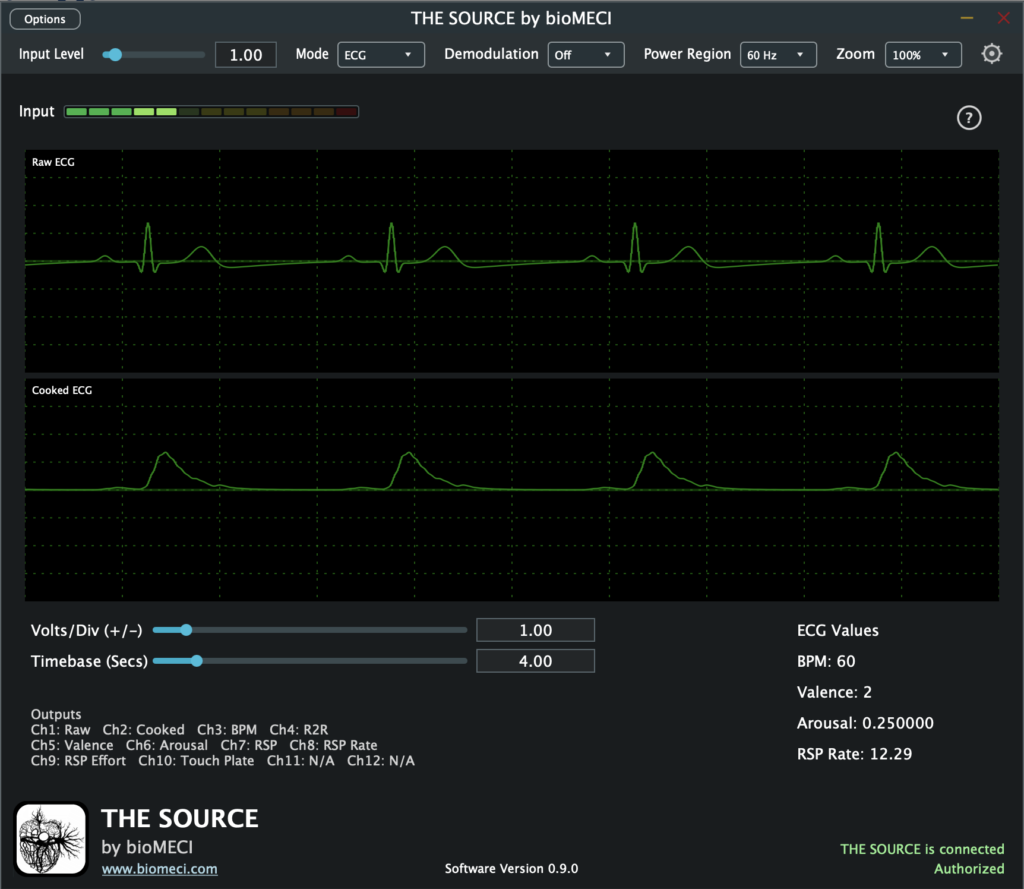
The Main View is the primary monitoring and configuration window in THE SOURCE. It combines signal-mode selection, input monitoring, real-time visualization, mode-specific controls, calculated values, output-channel mapping, and application/device status in one view.
The Main View is mode-aware. Selecting ECG, EMG, EEG, EOG, or Custom updates the visible scope channels, mode-specific controls, calculated values, and output-channel labels without changing the view’s purpose: to provide a single place to monitor THE SOURCE and make the most-used signal and display adjustments.
1.1. Main Controls #
The controls across the top of the Main View define the active biophysical signal mode and several global operating settings.
| Control | Function |
| Mode | Selects the active biophysical signal mode. The available visualization, calculated values, controls, and output mapping update automatically when the mode changes. |
| Demodulation | Enables or disables demodulation. When Demodulation is ON Modulation should be ON on THE SOURCE. When Demodulation is OFF Modulation should be OFF on THE SOURCE. |
| Power Region | Selects the configured power-line frequency region used by THE SOURCE. 60Hz or 50Hz depending on the power standard in your location. |
| Zoom | Changes the user-interface scale. |
1.2. Input and Signal Display #
The Main View provides immediate feedback about the incoming signal and a live scope for the signals most relevant to the selected mode.
| Control/Display | Function |
| Input | Displays the current input level. |
| Input Level | Adjusts the input level. The available control range is 0.00-10.00. |
| Live Scope | Displays the active signal channels in real time. The channel set changes with the selected biophysical signal mode. |
| Volts/Div (+/-) | Controls the vertical scale of the live scope. Range: 0.01-10.00. |
| Timebase (Secs) | Controls the amount of time represented in the scope display. Range: 0.01-30.00 seconds. |
1.3. Signal Modes #
THE SOURCE adapts the Main View to the selected biophysical signal mode. Mode changes affect the scope channels, calculated-value display, output map, and any mode-specific controls.
1.3.1. ECG Mode #
ECG Mode displays the Raw ECG and Cooked ECG signals in the live scope. The calculated-value area presents BPM, Valence, Arousal, and RSP Rate. The Outputs display identifies the current channel assignment for all available outputs.
| Displayed Value | Description |
| BPM | Calculated heart rate in beats per minute. |
| Valence | Current valence value calculated by THE SOURCE. |
| Arousal | Current arousal value calculated by THE SOURCE. |
| RSP Rate | Current calculated respiration rate. |
1.3.2. EMG Mode #
EMG Mode displays the Raw EMG and Cooked EMG signals in the live scope. The value area identifies Raw as output 1 and Cooked as output 2.
1.3.3. EEG Mode #
EEG Mode displays RAW, DELTA, THETA, ALPHA, BETA, and GAMMA in the live scope. It also provides controls for defining an EEG band ratio and displays the processed EEG-band values.
| Control/Display | Function |
| Numerator | Selects the EEG band used as the numerator of the calculated band ratio. |
| Denominator | Selects the EEG band used as the denominator of the calculated band ratio. |
| EEG Ratio | Displays the currently selected numerator / denominator relationship and its calculated ratio. |
| Cooked EEG Signals | Displays the current processed Delta, Theta, Alpha, Beta, and Gamma values. |
1.3.4. EOG Mode #
EOG Mode displays the Raw EOG and Cooked EOG signals in the live scope. The value area identifies Raw as output 1 and Cooked as output 2.
1.3.5. Custom Mode #
Custom Mode displays the custom out signal and exposes additional filtering controls directly in the Main View.
| Control | Function |
| Power Region | Turns the Custom Mode power-region filter on or off. |
| Low Pass | Turns the low-pass filter on or off. |
| Low Pass frequency | Sets the Custom Mode low-pass cutoff frequency from 0.0-500.0 Hz. |
| High Pass | Turns the high-pass filter on or off. |
| High Pass frequency | Sets the Custom Mode high-pass cutoff frequency from 0.0-500.0 Hz. |
1.4. Audio Outputs #
The Audio Outputs display shows the current audio/output-channel mapping for the selected mode. Channels are presented as Ch1 through Ch12. Channels that are not used by the current mode are shown as N/A. The mapping updates automatically when the biophysical signal mode changes. Audio Outputs are available to your host application when using the VST3 plugin.
1.5. Status and Software Information #
The bottom of the Main View provides device and software status information. THE SOURCE displays the current authorization state and shows “Input not available” when the device is not authorized. The installed software version is displayed continuously. When an update is available, an Update Available link can be shown with the new version number.
| Display | Function |
| Authorization status | Shows the current device authorization state. |
| Input not available | Appears when the device is not authorized for input. |
| Software Version | Displays the installed THE SOURCE software version. |
| Update Available | Appears when a newer software version and download location are available. |
2. Simulator #
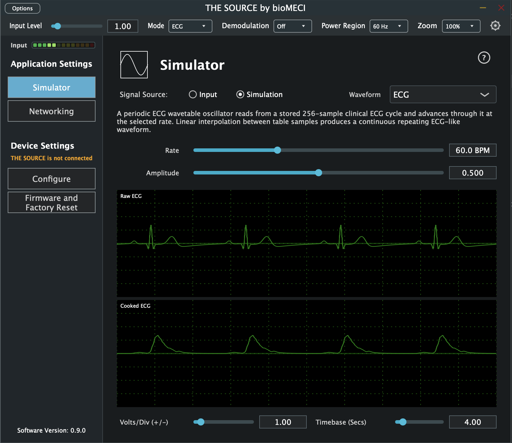
The Simulator provides a built-in signal source for testing THE SOURCE without requiring a live physiological input. It can switch between the hardware input and simulated signals, generate several waveform types, and display the resulting raw and processed signals in the same real-time scope used for monitoring. Input is available only when the device is authorized. If the device is not authorized, the Simulator displays “Input not available when not authorized” and automatically uses Simulation.
To use the Simulator, select Simulation under Signal Source, choose a waveform, and adjust its available rate/frequency/speed and amplitude controls. The generated signal is processed by THE SOURCE and can be observed in the live scope. Switching the application’s biophysical signal mode automatically updates the default simulator waveform and the scope channel layout.
2.1. Signal Source #
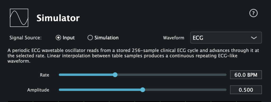
Signal Source selects whether THE SOURCE processes the live hardware input or the internal simulator.
| Control | Function |
| Input | Uses the signal arriving from THE SOURCE hardware. |
| Simulation | Uses the internally generated simulator signal. |
2.2. Mode-Aware Defaults #
When the biophysical signal mode changes, the Simulator automatically selects a corresponding default waveform. The waveform can then be changed manually from the Waveform menu if desired.
| THE SOURCE Mode | Default Simulator Waveform |
| ECG | ECG |
| EMG | EMG |
| EEG | EEG |
| EOG | EOG |
| Custom | Sine |
2.3. Waveform #
The Waveform menu selects the signal generated by the simulator. The available choices are Sine, Square, Triangle, ECG, EMG, EEG, and EOG. The Simulator displays a short description of the active simulation algorithm beneath the waveform controls. This description updates automatically when a different waveform is selected.
| Waveform | Simulation Method |
| Sine | A pure sine-wave oscillator at the selected frequency and amplitude. |
| Square | A two-state waveform alternating between positive and negative amplitude at the selected frequency. |
| Triangle | A piecewise-linear waveform that ramps between positive and negative amplitude. |
| ECG | A periodic ECG wavetable oscillator based on a stored 256-sample clinical ECG cycle with linear interpolation between table samples. |
| EMG | Broadband white noise shaped by three cascaded second-order 3 kHz Chebyshev Type-II low-pass filters and controlled by a sinusoidal amplitude envelope. |
| EEG | A five-component additive oscillator bank using components at 1, 6, 10, 18, and 33 Hz with self-amplitude modulation and independent scaling. |
| EOG | A horizontal eye-position model producing fixation plateaus, rapid saccades, reading-like stepped gaze positions, a return saccade, slow drift, and low-level noise. |
2.4. Waveform Controls #
Amplitude controls the simulator output level from 0.000 to 1.000. The second waveform control changes according to the selected waveform.
| Waveform | Control | Range / Behaviour |
| Sine / Square / Triangle | Frequency | 0.00 – 500.00 Hz |
| ECG | Rate | 20.0 – 140.0 BPM |
| EMG | Envelope | 0.10 – 2.00 Hz |
| EEG | Frequency | Disabled; the EEG simulator uses its fixed oscillator-bank frequencies. |
| EOG | Speed | 0.25 – 4.00 x |
2.5. Live Scope #
The scope displays the signals produced after the selected simulated input passes through THE SOURCE processing. Its channel labels follow the active biophysical signal mode.
| Mode | Scope Channels |
| ECG | First two ECG output channels (Raw and Cooked). |
| EMG | First two EMG output channels (Raw and Cooked). |
| EEG | RAW, DELTA, THETA, ALPHA, BETA, GAMMA. |
| EOG | First two EOG output channels (Raw and Cooked). |
| Custom | One channel out. |
2.6. Scope Controls #
| Control | Function |
| Volts / Div (+/-) | Sets the vertical scope scale from 0.01 to 10.00. |
| Timebase (Secs) | Sets the displayed time window from 0.01 to 30.00 seconds. |
3. Networking #
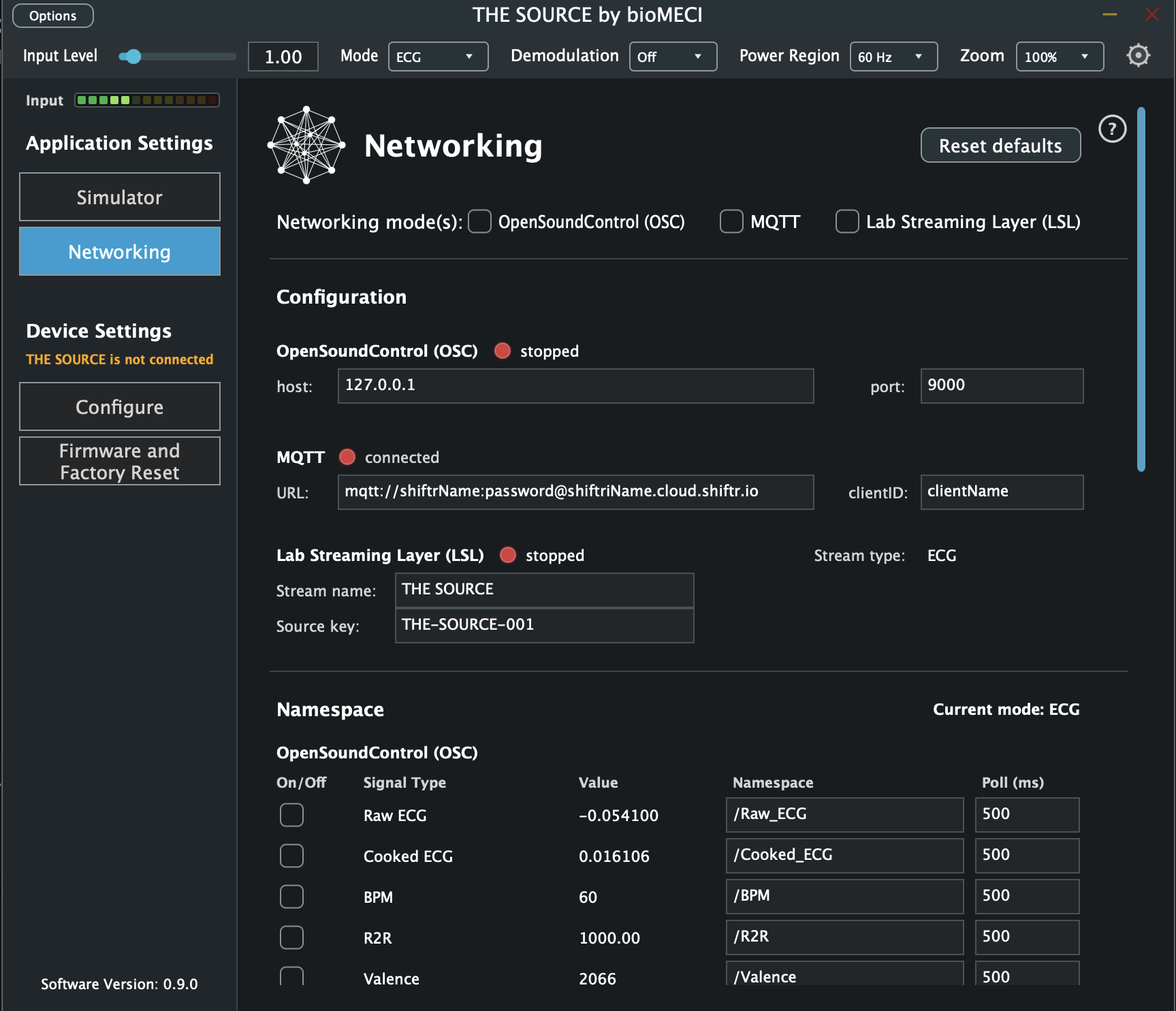
The Networking tab provides real-time network access to signals and derived data generated by THE SOURCE. Data can be transmitted simultaneously using Open Sound Control (OSC), MQTT, and Lab Streaming Layer (LSL).
Each protocol is configured independently. You can enable or disable OSC, MQTT, and LSL separately, and each protocol has its own per-signal controls in the lower portion of the Networking tab.
3.1. Networking Modes #
You can enable or disable each networking mode by checking the toggles at the top.
Enabling or disabling a networking protocol does not alter the underlying signal processing performed by THE SOURCE. It only determines which signals are made available to external applications.
3.2. Reset Defaults #
Reset defaults restores the Networking tab’s default configuration, including protocol settings, per-protocol namespaces and polling intervals, LSL channel names, and LSL configuration.
3.3. Open Sound Control (OSC) #
Open Sound Control (OSC) is a message-based communication format widely used in audio, interactive media, creative coding, and real-time multimedia applications. OSC identifies values using hierarchical addresses beginning with /, making it convenient for applications such as Max, Pure Data, SuperCollider, TouchDesigner, Unity, and other network-enabled environments.
To learn more, please visit the OpenSoundControl website.
When OSC is enabled, THE SOURCE sends each selected signal to the configured Host and Port. Host specifies the destination IP address. 127.0.0.1 sends OSC to another application running on the same computer. Port specifies the destination network port. The default is 9000.
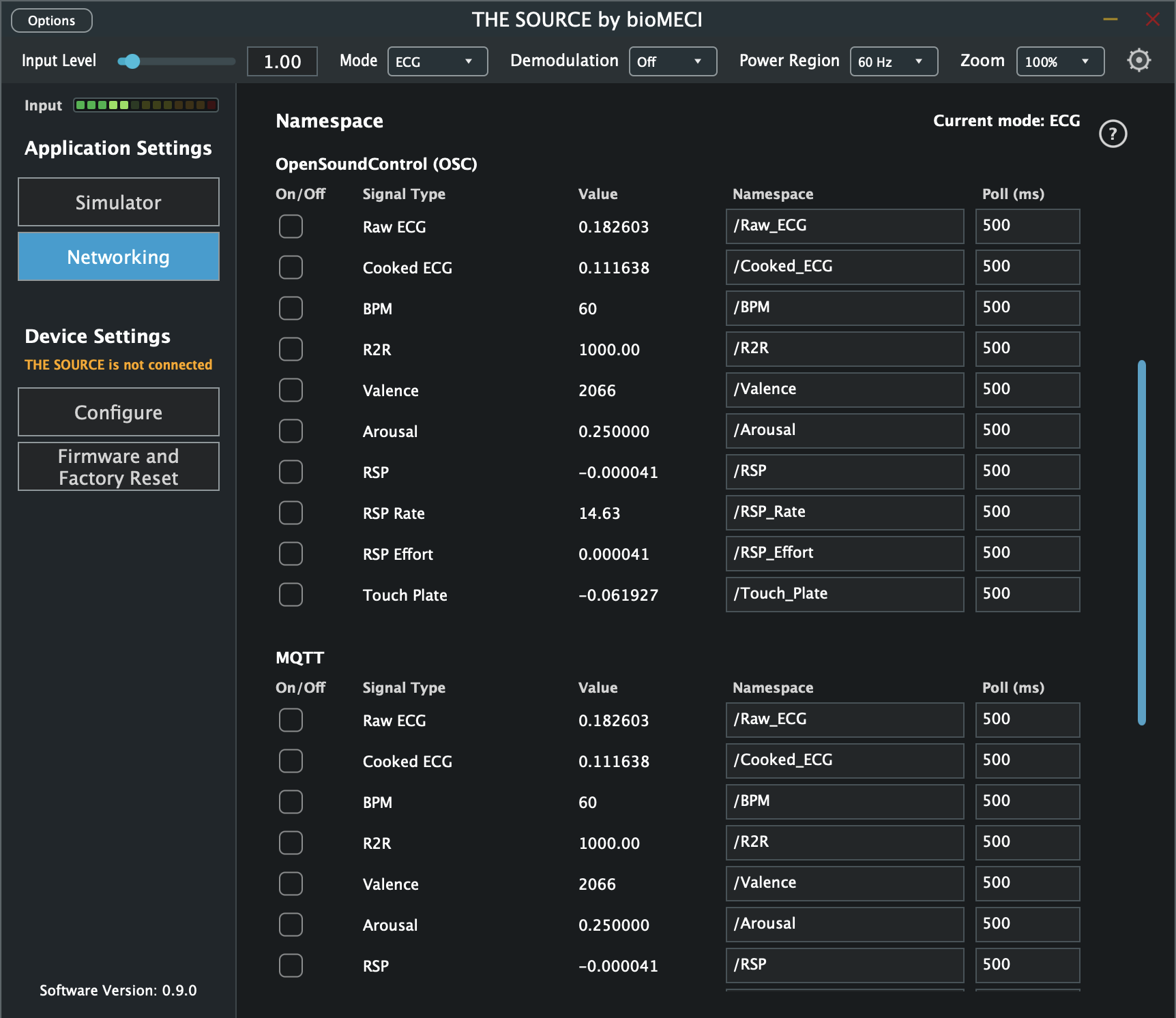
Each signal has its own OSC Namespace and OSC Poll (ms) value. These settings are independent of MQTT. For example, Raw ECG may be transmitted as /Raw_ECG. A Poll setting of 20 ms sends the current value approximately every 20 ms.
3.4. Message Queuing Telemetry Transport (MQTT) #
MQTT is a lightweight publish/subscribe messaging protocol suitable for distributing THE SOURCE data to networked applications, remote systems, IoT infrastructure, and cloud services.
To learn more, please visit MQTT.org.
When MQTT is enabled, THE SOURCE publishes selected signals through the configured MQTT broker. URL specifies the MQTT broker and connection information. Client ID identifies THE SOURCE application to the broker. The connection indicator shows the current MQTT connection state. Each signal has its own MQTT Namespace and MQTT Poll (ms) value. These settings are independent of OSC, so the same signal can use different addresses and different transmission intervals for the two protocols.
For an example of an MQTT broker for artists, visit: Shiftr.io
3.5. Lab Streaming Layer (LSL) #
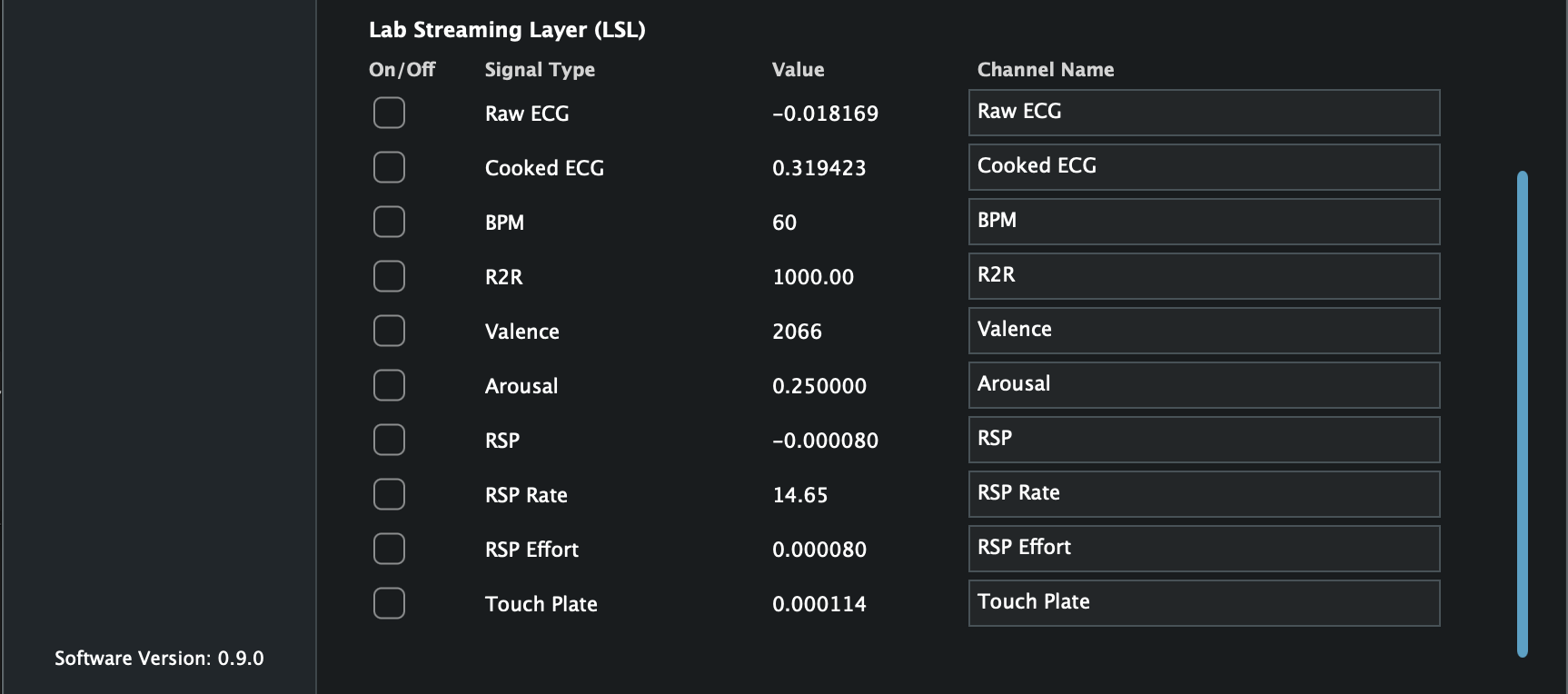
Lab Streaming Layer (LSL) provides synchronized streaming of time-series data between applications and computers. It is particularly suited to physiological signals, experimental systems, multimodal recording, and research applications.
The Lab Streaming Layer documentation website provides a detailed description of LSL and how to use it.
Unlike OSC and MQTT, LSL is not controlled by a polling interval. Enabled channels are transmitted as a continuous LSL time-series stream from THE SOURCE. In the current implementation, the stream has a nominal sampling rate of 2000 Hz and uses float32 channel values.
The LSL configuration includes:
| Control | Function |
| Stream Name | Identifies the THE SOURCE stream to LSL clients. |
| Source Key | The LSL source_id: a stable, unique identifier for the source. Example: THE-SOURCE-001. |
| Stream Type | Automatically follows the current signal mode: ECG, EMG, EEG, EOG, or Custom. |
| Status | Indicates whether the LSL outlet is currently streaming. |
Compatible applications automatically discover LSL streams and do not require OSC-style host and port settings. NOTE: The Source Key should be stable and unique on the LSL network and should not simply duplicate the Stream Name.
3.6. LSL Recording and Viewing #
For a simple LSL recording workflow, bioMECI currently documents LabRecorder (LSL) for recording LSL streams to XDF and SigViewer for opening and inspecting the recorded XDF file. These are independent third-party tools and are not required for THE SOURCE to transmit LSL.
The workflow is as follows: THE SOURCE transmits LSL → LabRecorder (LSL) records and saves the recording as an XDF file → SigViewer allows you to view and playback the file. LSL receiver applications can subscribe to multiple streams simultaneously. This allows signals from several THE SOURCE devices to be combined with data from other LSL-compatible devices and recorded concurrently within a synchronized session.
See the following website for a list of LSL viewers and compatible applications.
3.7. Signals #
The lower portion of the Networking interface is divided into independent OSC, MQTT, and LSL sections. Signal Type and Value are display-only; the protocol-specific controls determine how each signal is transmitted.
| Section | Controls |
| OpenSound | On/Off · Signal Type · Value · Namespace · Poll (ms) |
| MQTT | On/Off · Signal Type · Value · Namespace · Poll (ms) |
| Lab Streaming Layer (LSL) | On/Off · Signal Type · Value · Channel Name |
3.8. Polling and Streaming #
OSC and MQTT periodically read the current value of an enabled signal and transmit it according to their own protocol-specific Poll (ms) setting. For example, OSC could transmit Cooked ECG every 20 milliseconds (ms) while MQTT publishes the same value every 500 milliseconds (ms).
LSL instead carries enabled channels as a continuous time-series stream and is not affected by either OSC Poll or MQTT Poll. Multiple enabled LSL channels are transmitted together in the same stream, with their individual Channel Name metadata identifying them to compatible LSL clients.
This allows THE SOURCE to use the same signal simultaneously for creative/networked communication through OSC or MQTT and for synchronized recording or research workflows through LSL.
For OSC and MQTT, Namespace and Poll (ms) are independent. Changing the OSC settings does not change MQTT, and changing MQTT does not change OSC. LSL Channel Name is also independent of both network namespaces.
Changing a Namespace or LSL Channel Name only changes how a signal is identified externally; it does not alter the underlying signal or processing performed by THE SOURCE. LSL channel names may contain spaces, for example Raw ECG and Cooked ECG.
A single signal could therefore be configured simultaneously as:
| Setting | Example |
| Signal Type | Cooked ECG |
| OSC Namespace | /Cooked_ECG |
| OSC Pool | 20 ms |
| MQTT Namespace | /ecg/processed |
| MQTT Poll | 500 ms |
| LSL Channel Name | Cooked ECG |
3.9. Signal Types #
The available signals automatically change according to the currently selected signal mode. The Current Mode indicator identifies the active mode.
3.9.1. ECG Mode #
| Signal | Description |
| Raw ECG | Unprocessed ECG signal. |
| Cooked ECG | Processed and filtered ECG signal. |
| BPM | Calculated heart rate in beats per minute. |
| R2R | Interval between successive detected R-peaks. |
| Valence | Derived valence value calculated by THE SOURCE. |
| Arousal | Derived arousal value calculated by THE SOURCE. |
| RSP | Respiration signal derived from the physiological signal. |
| RSP Rate | Calculated respiration rate. |
| RSP Effort | Derived measure of respiration effort. |
| Touch Plate | Current value of the touch-plate input. |
3.9.2. EMG Mode #
| Signal | Description |
| Raw EMG | Unprocessed electromyographic signal. |
| Cooked EMG | Processed EMG signal. |
3.9.3. EEG Mode #
| Signal | Description |
| Raw Band | Broadband EEG signal before individual band processing. |
| Raw Delta | Raw Delta-band signal. |
| Cooked Delta | Processed Delta-band value. |
| Raw Theta | Raw Theta-nad signal. |
| Cooked Theta | Processed Theta-band value. |
| Raw Alpha | Raw Alpha-band signal. |
| Cooked Alpha | Processed Alpha-band value. |
| Raw Beta | Raw Beta-band signal. |
| Cooked Beta | Processed Beta-band value. |
| Raw Gamma | Raw Gamma-band signal. |
| Cooked Gamma | Processed Gamma-band value. |
| Ratio | Derived EEG band-ratio value. |
3.9.4. EOG Mode #
| Signal | Description |
| Raw EOG | Unprocessed electrooculographic signal. |
| Cooked EOG | Processed EOG signal. |
3.9.5. Custom Mode #
| Signal | Description |
| Out | Output signal generated by the current custom signal configuration. |
3.10. Networking Resources #
| Protocol/Tool | Resource |
| OSC | OpenSoundControl Specification 1.0 |
| MQTT | MQTT specifications/OASIS MQTT Version 5.0 |
| MQTT broker example | Shiftr.io |
| LSL | Lab Streaming Layer documentation |
| LSL viewers | LSL viewers and compatible applications |
| LSL recording | LabRecorder |
| XDF viewing | SigViewer |
4. Configuration #
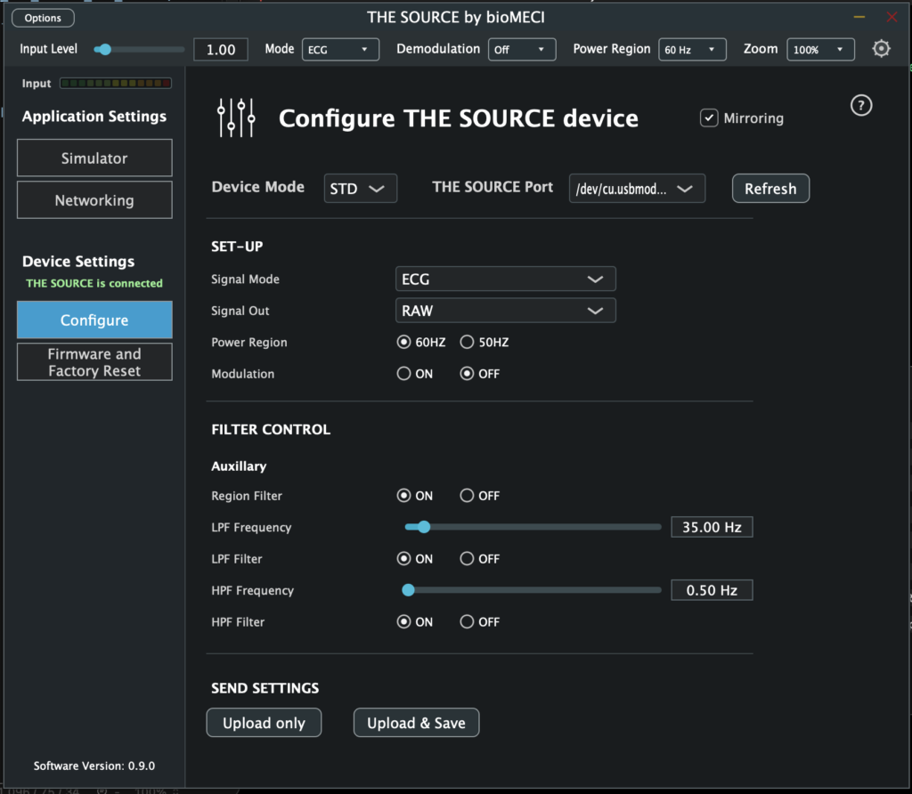
The Configuration window provides access to the operating settings stored by THE SOURCE device. It is organized into Standard, Advanced, and Developer device modes so that routine signal configuration is kept separate from lower-level hardware controls. Settings can be read from THE SOURCE, edited in the application, uploaded to the device, and saved to the device when required.
For routine operation, select STD, choose the Signal Mode and Signal Out, adjust filtering if needed, and upload the configuration. ADV exposes the preamplifier and PWM controls for more detailed signal-path configuration. DEV is intended for low-level hardware setup and diagnostics, including direct switch, UART, and Chop controls.
4.1. Device Mode #
Device Mode determines how much of the device configuration is exposed. Changing Device Mode changes the controls shown in the Configuration window; it does not itself select the physiological signal mode.
| Mode | Available Controls |
| STD | Set-Up and Filter Control. |
| ADV | Standard controls plus Preamp Control and PWM Control. |
| DEV | Advanced controls plus the individual hardware Switches, UART, and Chop controls. |
4.2. Mirroring and Refresh #
| Control | Function |
| Mirroring | Controls whether configuration-mode changes are mirrored by the application/device integration. |
| Refresh | Reads the current configuration from THE SOURCE. The control is available when the device is connected. |
4.3. Set-Up #
Set-Up defines the active signal configuration and the signal routed to the selected output path.
| Control | Function |
| Signal Mode | Selects ECG, EMG, EEG, EOG, or one of five user banks (Bank 1–Bank 5). Selecting ECG, EMG, EEG, or EOG applies the corresponding signal preset; selecting a bank recalls its stored configuration locally. |
| Signal Out | Selects the signal produced by the current mode. The available choices depend on Signal Mode. |
| Bank Name | Appears when a user bank is selected. Bank names are limited to nine characters. |
| Power Region | Selects 60 Hz or 50 Hz operation. |
| Modulation | Turns modulation on or off. |
| Signal Mode | Signal Out choices |
| ECG | RAW, COOKED, RSP, TOUCH, CUSTOM |
| EMG | RAW, COOKED, CUSTOM |
| EEG | RAW BAND, DELTA RAW/COOKED, THETA RAW/COOKED, ALPHA RAW/COOKED, BETA RAW/COOKED, GAMMA RAW/COOKED, RATIO |
| EOG | RAW, COOKED, CUSTOM |
| Bank 1-5 | CUSTOM |
When EEG RATIO is selected, an EEG Ratio control appears. The numerator and denominator can each be selected from DELTA, THETA, ALPHA, BETA, and GAMMA.
4.4. Filter Control #
Filter Control configures the biopotential and auxiliary signal paths. The auxiliary controls are always shown. Biopotential filter controls are shown when a Custom signal output or user bank is selected.
| Control | Function |
| Region Filter | Turns the region filter on or off for the selected signal path. |
| LPF Frequency | Sets the low-pass filter frequency using the supported stepped frequency values. |
| LPF Filter | Turns the low-pass filter on or off. |
| HPF Frequency | Sets the high-pass filter frequency using the supported stepped frequency values. |
| HPF Filter | Turns the high-pass filter on or off. |
4.5. Preamp Control (ADV DEV modes) #
Preamp Control is available in ADV and DEV modes. These controls configure the analogue preamplifier signal path and are synchronized with the underlying hardware switch states.
| Control | Choices/Function |
| Input | PREAMP or AUX IN. |
| HPF | 0 Hz, 0.005 Hz, 0.05 Hz, 0.5 Hz, or 5 Hz. |
| AC/DC | AC or DC coupling. |
| ST1 Gain | x1, x2, or x10. |
| ST2 Gain | x1, x5, x10, or x100. |
| Total Gain | Displays the combined Stage 1 × Stage 2 gain. |
| ST2 Discharge | Turns Stage 2 discharge on or off. |
| ST2 0.005Hz HPF | Turns the Stage 2 0.005 Hz high-pass filter on or off. |
| Output | PREAMP, AUX IN, or PWM. |
4.6. PWM Control (ADV DEV modes) #
PWM Control is available in ADV and DEV modes and configures the device PWM signal source.
| Control | Function |
| Output | Selects ACTIVE IN or PWM. |
| PWM Frequency | Sets the PWM frequency using the supported stepped frequency values. |
| PWM Amplitude | Sets PWM amplitude from 0.00 to 1.00. |
| Waveform | Selects SINE, SQUARE, TRIANGLE, ECG, ECGCLINICAL, or EXTERNAL_ADC. |
4.7. Switches (DEV mode) #
DEV mode exposes the individual hardware switch states A, B, C, D, E, F, G, H, I, J, K, L, O, P, R, and S. These are low-level controls underlying the higher-level preamp and routing settings. For normal configuration, use the Preamp controls rather than changing individual switch states directly.
4.8. UART (DEV mode) #
UART controls are available in DEV mode for serial communication testing and diagnostics.
| Control | Function |
| Baud Rate | Selects 2400, 9600, 57600, 115200, 230400, 500K, 1M, 2M, or 4M. |
| UART Test | Turns UART test mode on or off. |
| RX Bytes/sec | Displays the current receive rate. |
| Received | Displays received UART test information. |
4.9. Chop (DEV mode) #
Chop controls are available in DEV mode and expose low-level modulation and diagnostic state.
| Control/Display | Function |
| PIN N State | Displays the current PIN N state. |
| USB Plug | Displays the current USB plug state. |
| Modulations | Turns modulation on or off. |
4.10. Sending Settings to THE SOURCE #
The SEND SETTINGS section determines how the edited configuration is transferred to the device. These controls are enabled when THE SOURCE is connected.
| Control | Function |
| Upload only | Uploads the current settings to THE SOURCE over CDC without invoking the save-and-reboot action |
| Upload & Save | Sends the current settings to THE SOURCE for saving and rebooting. |
Settings are considered changed when the current signal-defining configuration differs from the last synchronized configuration. User-bank names are associated with the active bank and can be edited before saving.
5. Firmware and Factory Reset #
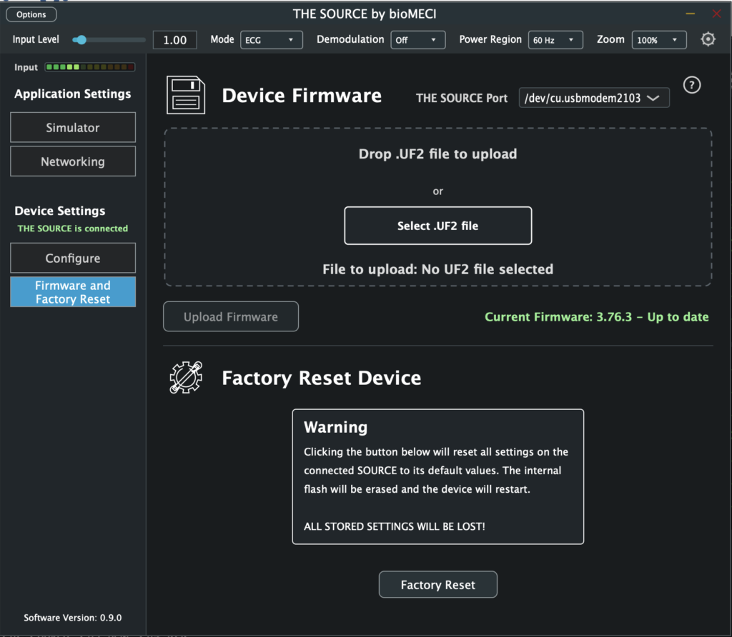
The Firmware and Factory Reset window provides two device-maintenance functions for THE SOURCE: installing device firmware from a UF2 file and restoring the device to its factory settings.
5.1. Device Firmware #
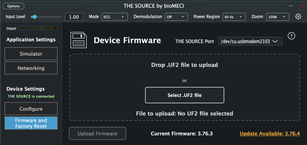
The Device Firmware section is used to select and upload a UF2 firmware file to THE SOURCE. A firmware file can be selected using the file-selection area or dropped directly onto it.
| Control/Display | Function |
| Firmware file selection | Click to browse for a UF2 firmware file, or drag a UF2 file onto the selection area. |
| File to upload | Displays the name of the currently selected firmware file. Before a file is selected, the display reads “No UF2 file selected.” |
| Upload Firmware | Reboots THE SOURCE into its bootloader and initiates copying of the selected UF2 firmware file. |
| Firmware status | Displays firmware-related status information. |
| Firmware update link | Can appear when an available firmware update and download location are provided. |
5.1.1. Selecting Firmware #
Select the firmware file by clicking the firmware-selection area and choosing a UF2 file, or by dragging the UF2 file directly onto the selection area. The selected filename is then shown under File to upload.
The Upload Firmware button is disabled until the application determines that firmware file is available.
5.1.2. Uploading Firmware #
After selecting the required UF2 file, choose Upload Firmware. THE SOURCE is rebooted into its bootloader and the selected UF2 file is copied to the device. The status area is used by the application to report firmware and upload information.
5.1.3. Knowing The Firmware Version And Available Updates #
The firmware status area displays the current device firmware/version state. When the application provides both update text and an update location, an underlined update link is displayed beside the firmware status. The link is hidden when no update is available.
5.2. Factory Reset THE SOURCE #
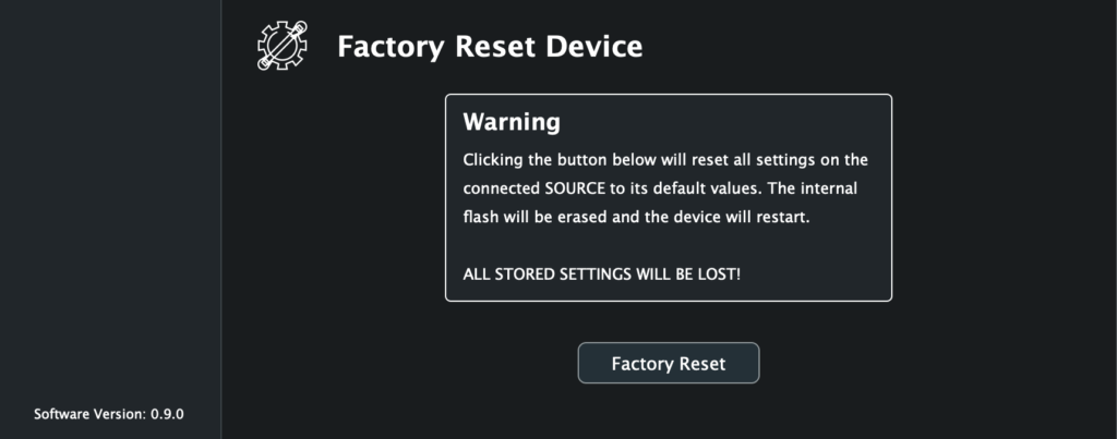
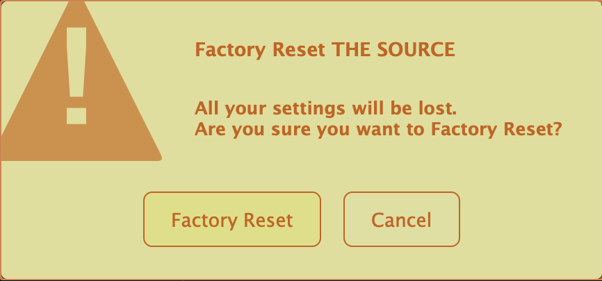
The Factory Reset Device section restores THE SOURCE factory settings and reboots the device. Because this operation replaces the current device configuration with the factory configuration, the interface presents a warning area before the Factory Reset control.
| Control / Display | Function |
| Warning | Displays the factory-reset warning presented by THE SOURCE. |
| Factory Reset | Restores THE SOURCE factory settings and reboots the device. |
| Reset Status | Displays the current factory-reset status or result. |
5.2.1. Performing a Factory Reset #
Choose Factory Reset to begin the reset operation. The control is available only when the application enables factory reset for the connected device. Status information is displayed beneath the button as the application reports the result of the operation.