1. Product Overview #
THE SOURCE is a modular wearable platform for full-spectrum*, real-time biosensing, designed for artistic research, neuroscience, human-computer interaction, affective computing, and physiological performance. It captures and analyses live biophysical signals from people, plants and fungi through integrated hardware and software tools, connecting directly with platforms such as Max9, SuperCollider, Ableton Live, TouchDesigner, PD and others that natively support VST audio plugins. Operating at the speed of interaction, The Source enables measurement, translation, and interpretation to occur as one seamless process.
* This includes: electrocardiogram (ECG), electromyogram (EMG), electroencephalogram (EEG), electrooculogram (EOG), electrogastrogram (EGG), ventilatory effort (RSP Effort), electrodermal activity (EDA), pulse plethysmogram (PPG), blood volume (BVP), and blood flow.
2. Hardware Overview #
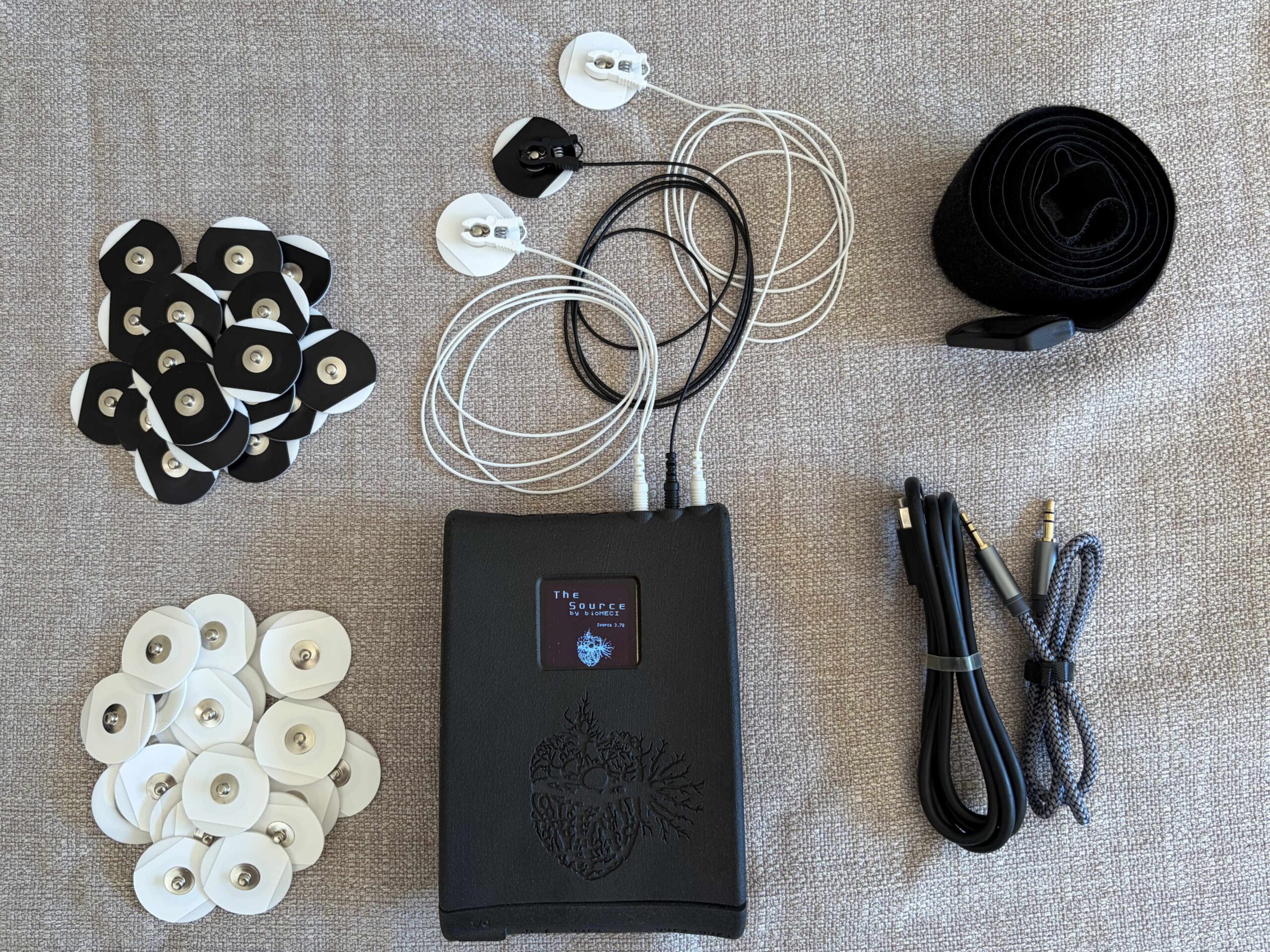
The picture above shows the basic components of THE SOURCE kit. From left to right, top to bottom, there are the electrodes (white and black for differentiating between inputs), electrode clip-on leads (two white, one black), THE SOURCE device, adjustable Velcro strap that can be placed around the waist, arms or legs, USB-C charging & data transfer cable, and 3.5mm audio cable.
3. Connecting to THE SOURCE #
AUX OUT – 3.5mm stereo plug (tip: 3.3V, ring: Output, shield: G). Output for sample-accurate (synchronised) stimulus, trigger and test signals. +/- 1V nominal output range.
AUX IN – 3.5mm stereo plug (tip: 3.3V, ring: Input, shield: G). Input for SOURCE transducers. +/- 1.6 V to +/- 1.6 mV single-ended max input ranges – over gains of 1 to 1000.
ELECTRODE LEADS IN – (1.5mm female – touchproof). Connect three (3) electrode leads (IN+ Lead / IN Reference Lead / IN- Lead). +/- 80mV to +/- 80uV differential voltage max input ranges (IN+ to IN-) – over gains of 20 to 20,000.
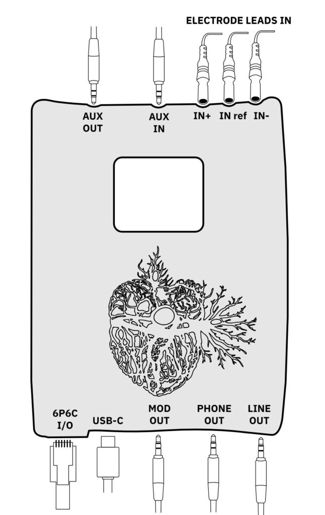
6P6C I/O – Modular 6P6C connector for accessory modules and expanders, UART (Tx/Rx), Differential Analog Driver Output (mimic of LINE OUT), and Protected Battery Power Output (3.7V).
USB-C – Power, charging, and USB Data I/O.
MOD OUT – Modulation Output – 3.5mm stereo plug (tip: Mod Output, ring: N/C, shield: G). 4kHz (4.096kHz) amplitude-modulated output for sound card interfacing – AC Coupled. +/- 1 V nominal output and adjustable range (0-2 V p-p).
PHONE OUT – Headphone Drive Output – 3.5 mm stereo plug (tip: L, ring: R, shield: G). L and R are differential analog driver outputs from THE SOURCE device – Headphone driver outputs are AC – coupled. +/- 1V nominal output range.
LINE OUT – Line-level Drive Output – 3.5 mm stereo plug (tip: L, ring: R, shield: G). L and R are differential analog line driver outputs from THE SOURCE device. Line-level driver outputs are DC – coupled. +/- 1V nominal output range.
4. Connecting to Computer #
4.1. Option 1 – USB-C #
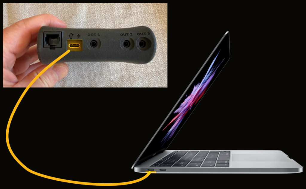
Connect THE SOURCE directly to a computer using the USB port. THE SOURCE will appear as an audio input device on your computer. THE SOURCE is a dual-channel device that outputs the biopotential on Channel 1 and the auxiliary output on Channel 2.
4.2. Option 2 – Wireless guitar and microphone transmitter #
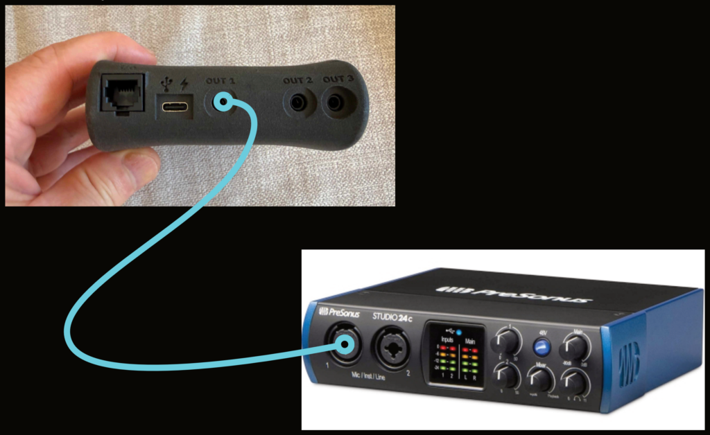
This setup will require longer cable runs and working with wireless signal transmitters. To connect from THE SOURCE to a computer, use a 3.5mm (1/8″) cable from the OUT 1 (modulation out) on THE SOURCE to an input on the Audio Interface. Modulation is helpful when interfacing THE SOURCE to sound cards, sound interfaces, wireless (guitar) transmitters, and general computer audio inputs when capturing biopotential and other biophysical signals.
Typically, the above input audio devices have a constrained frequency sensitivity of 5Hz (or higher) start of range – typically 20Hz to 20kHz. The problem in interfacing to the above-listed devices is that the majority of biopotential and other biophysical signals have a low-end frequency range
extending to DC (or close to DC). In these cases, to capture biopotential or other biophysical signals where most of the signal energy is below 20 Hz, use the modulation output of THE SOURCE and demodulate it on the other end using the VST plugin to capture the signal.
5. Connecting to a Body #
5.1. Electrode placement. #
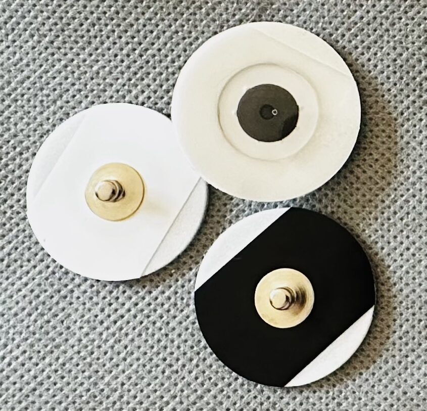
Electrodes are sticky, disposable pads with a metal piece that an electrode lead clips onto. Never use electrodes more than once. To differentiate between the leads, we recommend using a black electrode for the reference lead (IN ref), and white ones for the positive (IN +) and negative (IN -) leads. Do not place the black electrode in the measurement path between the two white electrodes.
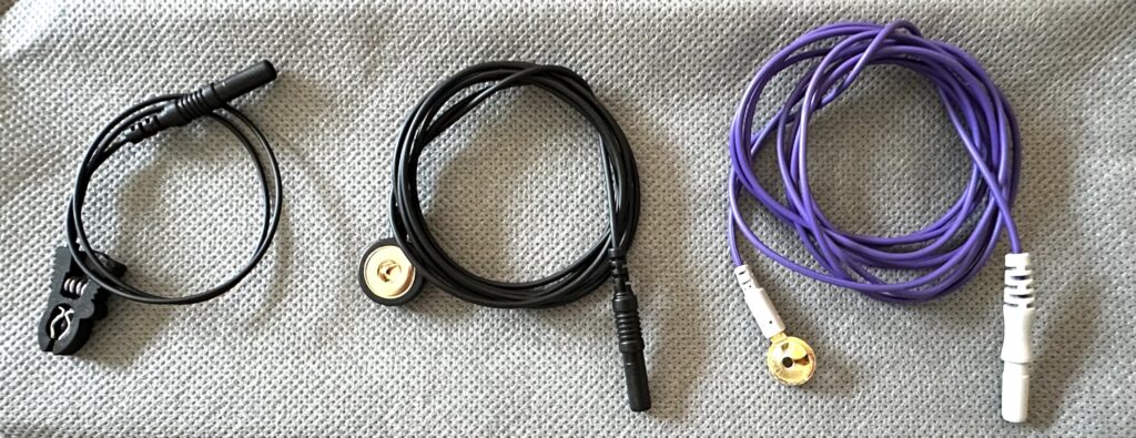
When connecting electrode leads to electrodes, make sure the connection is secure. The clip on the electrode lead should seal in place. Gently tug on the electrode lead to make sure it doesn’t disconnect easily. You will find a more comprehensive guide on electrode placement in our menu. The gold-cup electrodes are used with conductive gel (for example, TEN20), which must be applied generously to ensure the metal part does not touch the skin.
5.2. ECG (electrocardiogram) #
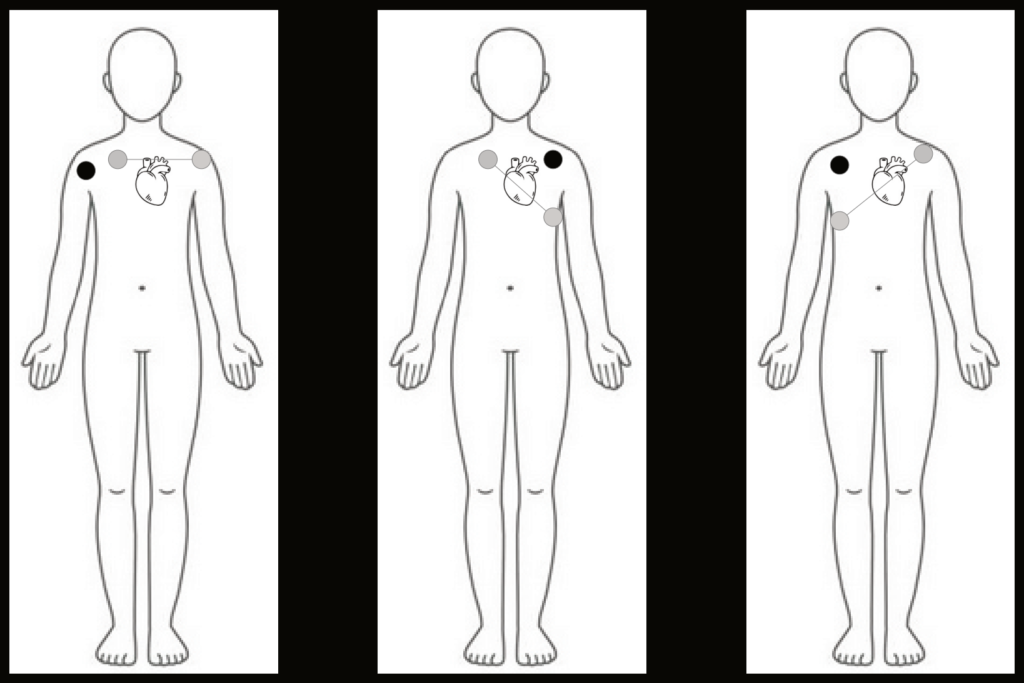
The dots above show electrode placement; the black dot represents the IN Ref (Reference) electrode and lead, and the grey dots represent the IN+ and IN- electrodes and leads. You can record the heart from multiple directions, depending on what details you want to capture. For general heart signal capture, all three electrode placement systems work well, but LEAD I is easiest to apply over clothes. LEAD II and LEAD III will likely capture less skeletal muscle in the signal, especially when placed closer to the heart.
6. Software #
The primary tool for working with THE SOURCE is a VST3 plugin that is available for Mac, Windows, and Linux. VST3 plugins can be used in most audio and multimedia applications such as Max9, TouchDesigner, PD, SuperCollider, Ableton Live, etc. See the VST doc for details.
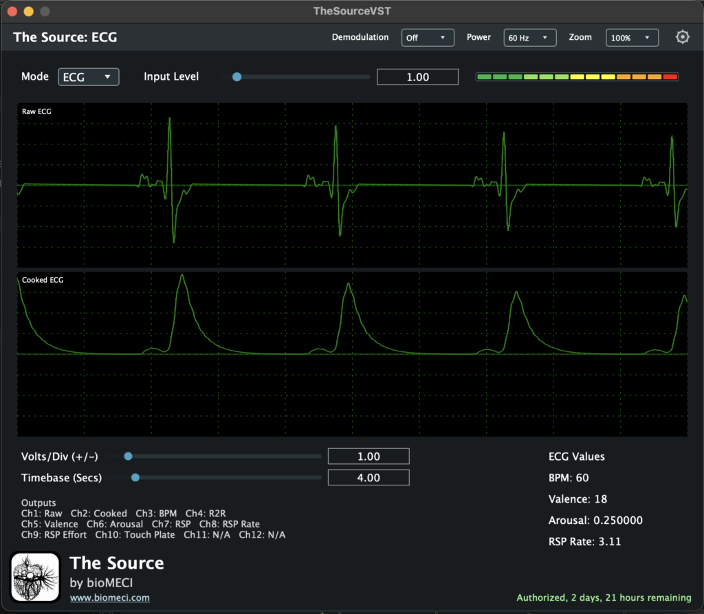
7. Max9 Examples #
The following examples show how to use the VST in MAX. We also offer many templates for audio and multimedia applications such as Max, TouchDesigner, PD, SuperCollider, and Ableton Live, available in Application-based examples.
7.1. ECG (electrocardiogram) mode #

You can access example files from our Member page by signing in. Once you download and open the Max patch, turn on audio in the lower-right corner for the patch to work.
In the top-left corner, you can control the patch’s inputs and outputs. Select the input device that THE SOURCE is connected to. You can also select the output device you wish.
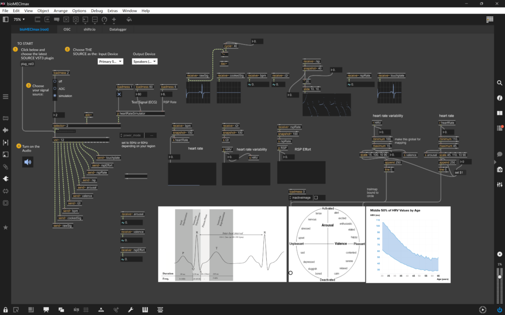
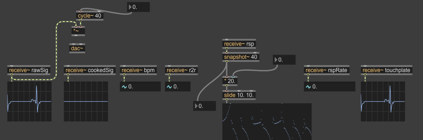
On the far left, controls the signal the patch sees: off, ADC (audio input), and simulation. All patches include a simulation that shows you what the signal should look like. The top-right side shows the ECG-derived signals coming from the VST plugin.
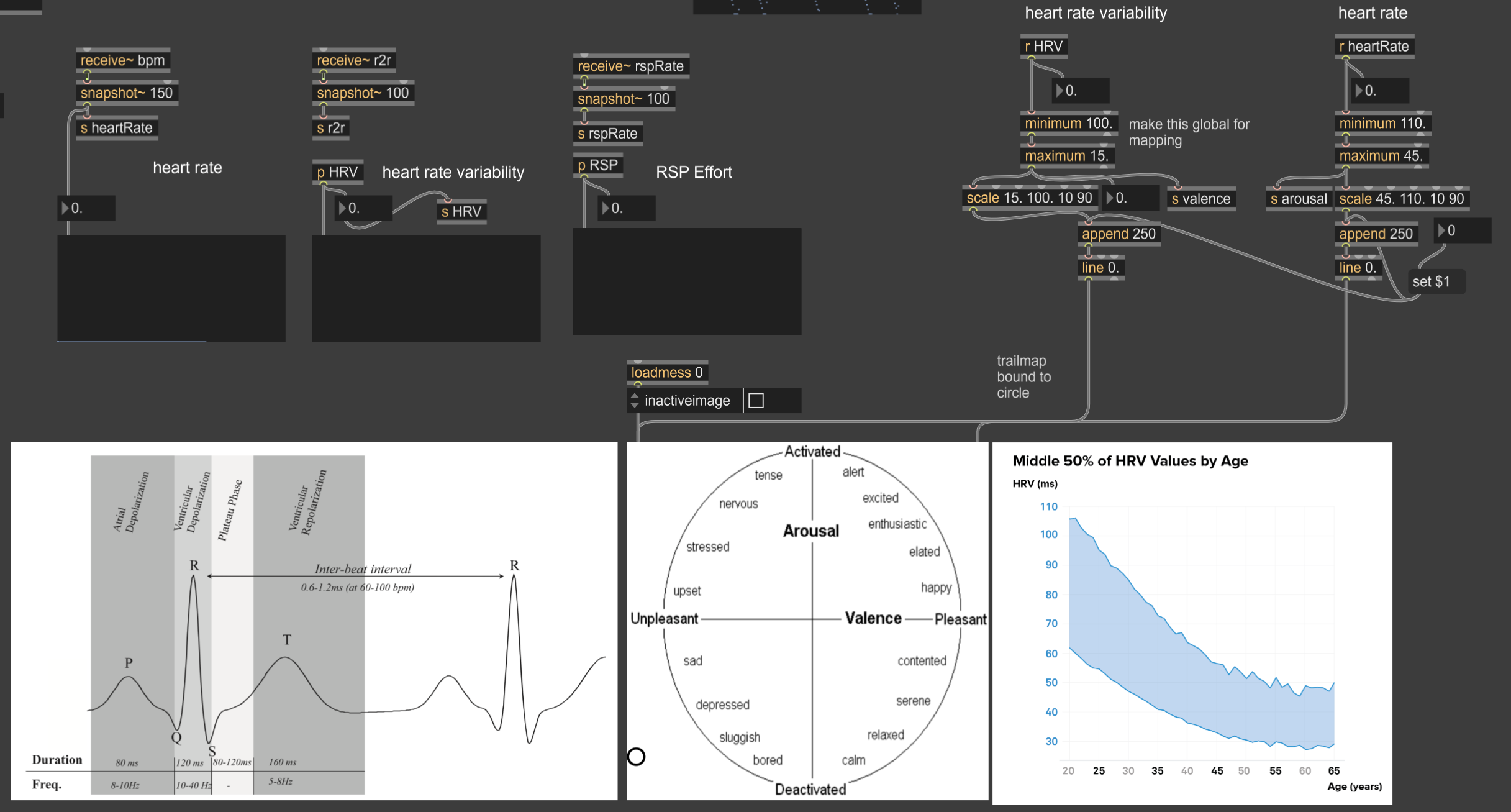
The bottom-right section presents a selection of higher-level analyses based on signals derived from the ECG.
7.2. EMG (electromyography) mode #
A base project allows you to derive raw and cooked EMG signals. EMG can capture a wide variety of signals, including skeletal muscle movement, face tracking, and respiration, depending on which groups you isolate. Please ask if you have ideas or questions.
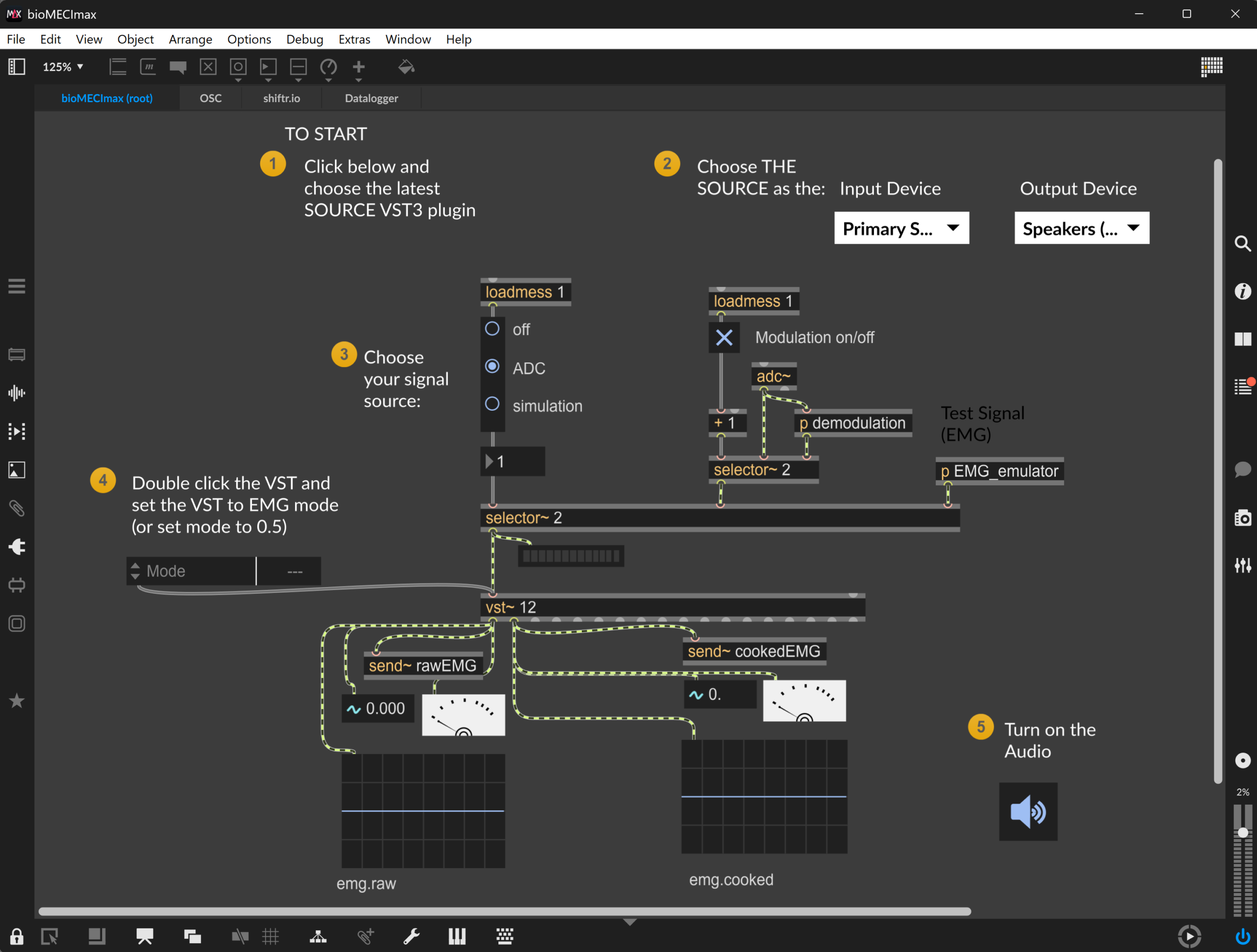
NOTE: To use EMG mode, you also need to switch THE SOURCE device to EMG mode.
7.3. EEG (electroencephalogram) mode #
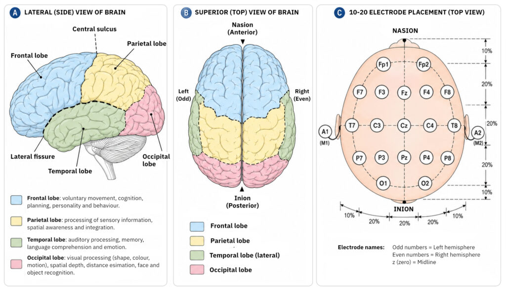
Electroencephalography (EEG) measures electrical activity in the brain. Locations vary, but for alpha detection, use the occipital lobes. Standard electrode placements include O1 to A2, with the Reference electrode at FP1; or O2 to A2, with the Reference at FP2. These setups require earclip electrodes at A1 and/or A2 to ensure stable, reliable recordings. However, recording at O1 or O2 can be challenging if the subject has a substantial amount of hair, which may interfere with electrode contact and signal quality.
A base Max9 project allows you to derive an array of EEG signals. This includes raw and cooked versions of Delta, Theta, Alpha, Beta and Gamma signals. You can tune the analysis with attack/decay controls. You can also compare brain waves to determine dominance by selecting and customising different Ratios.
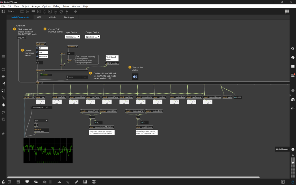
NOTE: To use EEG mode, you also need to switch THE SOURCE device to EEG mode.
8. THE SOURCE Modes #
In order to use THE SOURCE with the different VST patches above, it is important that THE SOURCE is in the same mode as the VST plugin.
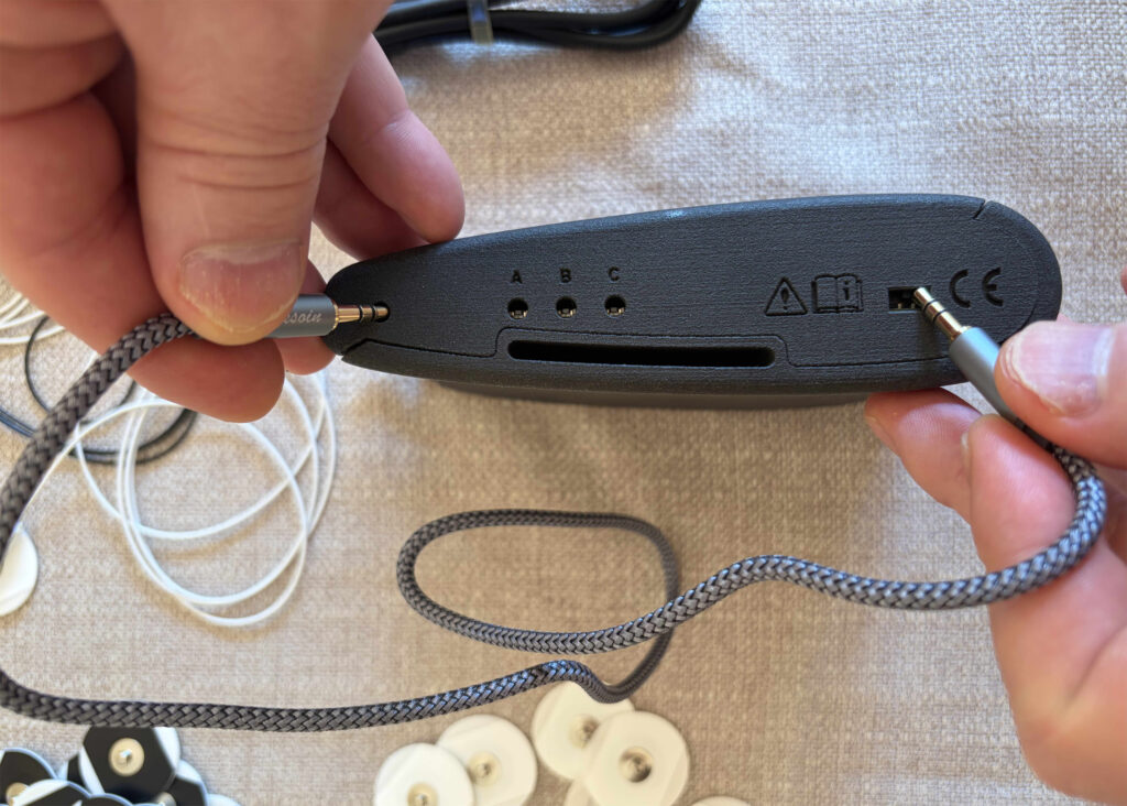
To change the mode, gently press the buttons inset on the side of THE SOURCE. You can use a 3.5mm plug end or another tool to help. THE SOURCE has three buttons: A, B, and C. Button A toggles between view mode and settings mode, button B changes which parameter is being changed, and button C changes the parameter itself.
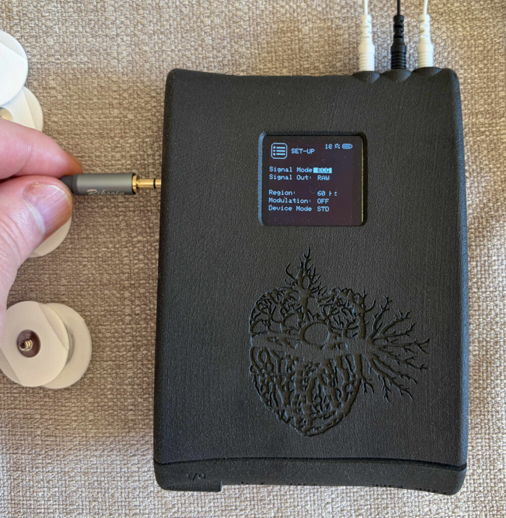
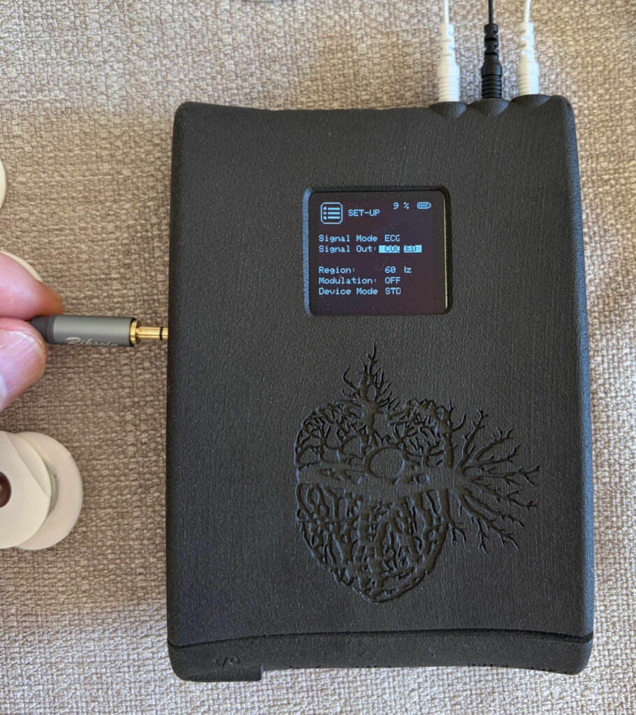
The current parameter being changed is highlighted. STD mode has four modes: ECG, EMG, EEG, and EOG. Press button C to cycle through them. Other things you can change include the output signal type (i.e., RAW or COOKED) [currently inactive], the power region (50 Hz or 60 Hz), and the Modulation (ON, OFF). See the latest firmware documentation for details.
8.1. Firmware updates #
Firmware is developed in C/C++ for RP2040 (dual-core MCU), using TinyUSB and FreeRTOS. Firmware modules are structured for low-latency biophysical signal acquisition and high-throughput streaming. Firmware updates are uploaded via .uf2 firmware files available for download from our website. Please contact our bioMECI team for support or to access files.
Firmware updates can be uploaded using the following procedure:
1. Put THE SOURCE device into firmware mode: With THE SOURCE off, plug the USB into your computer. Press the firmware button (the one at the top of the device on the left, or to the left of the three buttons, as shown in the image below). While holding it down, turn on THE SOURCE.
2. On a computer screen, a removable drive named RPI-RP2 should appear. (similar to when you load a removable drive). Copy or drag the .uf2 firmware file onto the RPI-RP2 drive. The drive will automatically disconnect, and THE SOURCE will restart using the new firmware.