1. Powering On #
When you power on THE SOURCE device, it opens to the Scope mode.
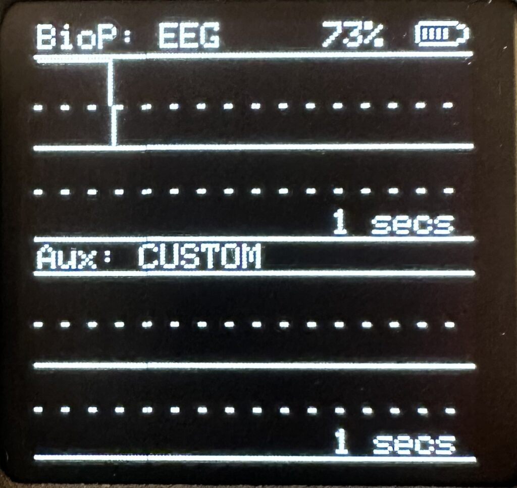
In the Scope mode, Biopotential Input (BioP) is displayed at the top. You can ignore the bottom scope for now. Currently, the Scope is in Developer Mode, and if you press the B button, the Scope will cycle through different device modes. This is for testing and development. For basic use, the best mode is the one pictured here. If, for some reason, you press B by accident, keep pressing until you see the Scope mode that matches what you see above.
2. About Screen Navigation #
The first time you power on THE SOURCE device, it starts in Standard Mode with ECG selected and all recommended settings automatically applied. Once you save your settings, the device remembers everything–including the selected signal source, device mode, filters, and other options–and restores them the next time it powers on.
The three buttons on THE SOURCE device (A, B, C), unless otherwise stated, map to the following controls:
● A = Move to the next screen
● B = Select an item on the current screen
● C = Change the selected item
Press A to cycle through screens. Screens not enabled by the current device mode are skipped automatically. THE SOURCE device modes control the configuration mode of THE SOURCE. Only screens available in the current mode will be shown.
Standard (STD) Mode. Is for everyday use and includes:
Scope → Set Up → Filter Control →Save Settings → Scope
Advanced (ADV) Mode. Advanced Mode adds Filter Control, Preamp Control, and PWM Control, resulting in:
Scope → Set Up → Filter Control → Preamp Control → PWM Control → Save Settings → Scope
Developer (DEV) Mode. Developer Mode adds Switches, UART Test, and Chop Control, resulting in:
Scope → Set Up → Filter → Preamp → Switches → PWM → UART → Chop → Save Settings → Scope
3. Screen Modes #
The documentation provided here is for Standard Mode. Standard Mode is designed for day-to-day operation of THE SOURCE and provides access to the essential controls needed to acquire and save biophysical signals. It offers a simplified interface that lets users quickly select a signal type, configure basic settings, and save their preferences without exposing the device’s more advanced engineering and development features.
3.1. Scope Screen #
The Scope screen displays the live biopotential signal and the AUX signal.
Button controls:
● A: move to the next main screen
● B: change the scope timebase
● C: change the scope view, where available
STD Mode (Standard)
STD Mode shows the normal two-channel Scope view displays: Top trace: selected biopotential signal and Bottom trace: AUX signal.
Labels:
BioP: ECG, BioP: EMG, BioP: EEG, BioP: EOG, or selected bank name.
Aux: CUSTOM
Controls:
● B: cycles the timebase
● C: for ECG only, toggles between the waveform scope and the ECG Metrics screen
ECG Metrics screen:
● IBI
● BPM
● HRV
● RSP Rate
For non-ECG signals, the Metrics screen is currently bypassed.
ADV Mode (Advanced)
ADV Mode uses the same normal two-channel Scope view as STD Mode displays: Top trace: selected biopotential signal; Bottom trace: AUX signal.
Labels:
BioP:
Aux: CUSTOM
Controls:
● B: cycles the timebase.
● C: for ECG only, toggles between the waveform scope and the ECG Metrics screen.
Other signal types currently stay on the standard waveform Scope.
DEV Mode (Developer)
DEV Mode adds diagnostic Scope views for checking internal signal routing.
Controls:
● B: cycles the timebase
● C: cycles Scope views
DEV scope views:
● MODE0: ADC1 BIOP / ADC3 AUX
● MODE1: ADC1 BIOP / ADC0 PWM
● MODE2: ADC3 AUX / ADC0 PWM
● MODE3: ADC1 BIOP / NOT USED
● MODE4: ADC0 PWM / NOT USED
● MODE5: ADC2 BATT / NOT USED
● MODE6: ADC3 AUX / NOT USED
For ECG in DEV Mode, C first shows the ECG Metrics screen, then continues through the diagnostic Scope views.
3.2. The Set Up Screen #
The Set Up screen is the easiest way to configure the device. Use B to move between settings and C to change them.
Signal Modality
Choose the signal source you want to work with.
Available options:
● ECG – Heart activity
● EMG – Muscle activity
● EEG – Brain activity
● EOG – Eye movement activity
● CUSTOM – a custom filter band. You can change this on the Filter Control screen; see below.
● Bank1-Bank5 – Your own saved presets
Selecting a built-in signal type automatically loads the recommended hardware configuration. Filter settings are based on the Signal Out; see below. Selecting a bank loads the settings previously saved in that bank.
Output Signal Mode ///CHECK!!!!
Choose an output signal for the above signal type.
Available options:
● ECG: RAW → COOKED → RSP → TOUCH → CUSTOM RAW→COOKED→
● EMG: RAW → COOKED → CUSTOM
● EEG: BAND → Dlt RAW → Dlt COOK → Tht RAW → Tht COOK → Alp RAW → Alp COOK → Bta RAW→ Bta COOK → Gam RAW → Gam COOK → RATIO* → CUSTOM
● EOG: RAW → COOKED→ CUSTOM
CUSTOM: Uses the current Biopotential LPF, HPF, and powerline filter settings from Filter Control; see below.
Notes:
– Signal Out changes what is shown on the scope and is sent through the biopotential output path.
– CUSTOM keeps the current analog switch configuration for the selected biosignal, but routes the DSP through the editable Filter Control settings.
– Aux is always controlled through Filter Control.
– Signal Out settings persist after reboot when settings are saved.
* Ratio
In EEG RATIO mode, an additional menu item appears that allows you to select the Numerator and Denominator for a ratio-based analysis, e.g. ALPHA/BETA or BETA/THETA.
Region
Sets the mains-noise filter for your region:
60 Hz → Canada, USA, Mexico, most of the Americas, South Korea, Taiwan, Parts of Japan
50 Hz → Europe, UK, Australia, New Zealand, China, India, most of Africa, Parts of Japan
Modulation
Turns signal chopping on or off. See note About Modulation below.
Device Modes
Controls the configuration mode of THE SOURCE. Only screens available in the current mode will be
shown.
Standard (STD) Mode
Is for everyday use and includes:
Scope → Set Up → Save Settings → Scope
Advanced (ADV) Mode
Advanced Mode adds Filter Control, Preamp Control, and PWM Control, resulting in:
Scope → Set Up → Filter Control → Preamp Control → PWM Control → Save Settings → Scope
Developer (DEV) Mode
Developer Mode adds, Switches, UART Test, and Chop Control, resulting in:
Scope → Set Up → Filter → Preamp → Switches → PWM → UART → Chop → Save Settings → Scope
3.3. The Filter Control Screen
///image here #
The Filter Control screen lets you edit the digital filters for the Biopotential and Aux signal paths. Use B to move between settings and C to change the selected value.
Region
Choose the powerline frequency for the notch filter.
Available options:
● 60 Hz – North America and other 60 Hz regions
● 50 Hz – Europe and other 50 Hz regions
This setting is shared by the Biopotential and Aux powerline filters.
Independent controls
Independent controls for Biopot and Aux include the following options:
● Region – ON/OFF
● LPF freq – Low-pass filter cutoff frequency
● LPF ON/OFF – Enable or bypass the low-pass filter
● HPF freq – High-pass filter cutoff frequency
● HPF ON/OFF – Enable or bypass the high-pass filter
A note about Biopotential Filters: Biopotential signal output CUSTOM mode keeps the selected hardware/switch configuration for a
particular signal but uses the editable Filter Control filters. These controls are only available when the selected Signal Out is CUSTOM. If the current Biopotential Signal Out is not CUSTOM, this section shows:
///IMAGE HERE
This means the selected Biopotential signal is using its built-in processing path, such as ECG RAW, ECG, COOKED, EEG ALPHA, or EOG COOKED. To edit the Biopotential LPF and HPF directly, go to the Set Up screen and change Signal Out to CUSTOM. For clarity, the Aux path is always controlled from the Filter Control screen.
Saving Filters
Changing LPF/HPF in Filter Control in either BioPot or Aux makes the current working settings dirty. To keep these settings after a boot, save them to one of Bank1-Bank5 when saving the settings; see below.
3.4. Saving Settings #
//IMAGE here
The Save Settings screen behaves differently depending on what is currently selected.
Saving a Built-In Preset
If you are using an unmodified built-in preset (for example, ECG) and there is no * next to its name:
● Press C
● The device saves that preset as the default startup source
● The device reboots
No bank is used. Next time the device powers on, it will start with that preset.
Modified Presets and Banks
If the source name shows a * (for example, ECG* or Bank3*), you have made changes that have not yet been saved. The * appears whenever you change settings such as:
● Filters
● Region
● Modulation
● Switch settings
● Other configuration options
The * disappears when:
● You save the settings, or
● You switch to a different source
Switching sources discards any unsaved changes.
Save to Bank
When saving a modified preset or an existing bank:
-> Step 1 – Choose a Bank
////IMAGE here
Press B to select:
● Bank1
● Bank2
● Bank3
● Bank4
● Bank5
Press C to choose the destination bank.
-> Step 2 – Name the Bank
////IMAGE here
You can edit the bank name:
● B = Move cursor
● C = Change character
● A = Save name and continue
If you’re saving from a built-in preset, the bank name is automatically filled with a suggested name such as ECG+, EMG+, EEG+, or EOG+. You can keep it or change it.
-> Step 3 – Save
Press A to:
● Write the settings to memory
● Reboot the device
On the next startup, the saved bank loads automatically.
-> Cancelling a Save
At either the Save Settings screen or the Save to Bank screen:
● Press A to cancel and return without saving any changes.
4. Appendix A: Uploading Firmware #
To put THE SOURCE into firmware mode: With THE SOURCE device turned off, plug THE SOURCE device into your USB port
● Press down THE SOURCE device firmware button (the one by the top of the device on the left – just above the three buttons)
● While holding the firmware button down, turn on THE SOURCE device
● A removable drive named RPI-RP2 should appear on the computer screen. (similar to when you load a removable drive)
● Copy or drag the .uf2 firmware file onto the RPI-RP2 drive.
● The drive will automatically disconnect, and THE SOURCE device will restart using the new firmware.
5. Appendix B: About Modulation #
Modulation is useful when connecting THE SOURCE device to audio signal equipment, such as:
● Audio interfaces and sound cards
● Computer microphone inputs
● Wireless guitar transmitters
● Other audio recording equipment
Most audio devices are designed to work in the range of approximately 20 Hz to 20 kHz, and therefore cannot capture the typical sub-audio range biological signals. Many biophysical signals–including ECG, EOG, respiration, and other sensor outputs–contain important information at frequencies that extend down to DC (0 Hz) or very close to it. When these signals are connected directly to an audio device, much of the low-frequency information is filtered out.
When Modulation is enabled, THE SOURCE device shifts the signal into a frequency range that audio hardware can transmit and record reliably. The recorded signal can then be restored to its original form using the accompanying VST plugin, which demodulates it
.
Use Modulation when:
● Connecting THE SOURCE through an audio interface or sound card.
● Collecting data from many THE SOURCE devices simultaneously and synchronously – number of devices is only limited by the availability of synchronized audio inputs to the computer.
● Using wireless audio transmitters.
● Recording through microphone or line-level audio inputs.
Modulation can be left off when:
● Using only the USB connection to THE SOURCE device.
● Using only software that communicates directly with THE SOURCE via USB.
● Using only the Headphone and/or Line outputs.
In general, if your signal path passes through equipment designed for audio rather than measurement, enabling Modulation will provide the best results. Additionally, if multiple THE SOURCE devices are intended for synchronized physiological measures – such as in cases of group physiology measures (plant/fungi/human synchronized measures) – then system architecture requirements specify Modulation outputs directed to multi-channel, synchronized, sound cards for input to the computer.